DAMON TSAI, Rudolph Technologies, Inc., Wilmington, MA
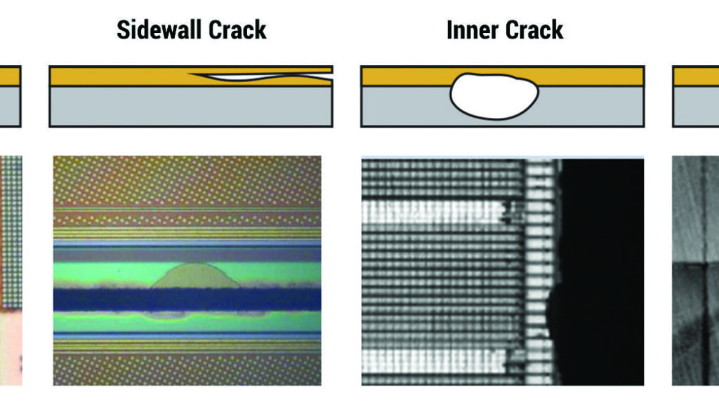
Die cracks come in several types (Figure 1), each requiring a different approach to optimize detection. Hairline cracks occur at the surface. They are small and shallow and show low contrast in inspection images. Sidewall cracks penetrate the die from the sidewall (the die edge), roughly in the plane of the die, and seem to be directly associated with the dicing process. Inner cracks are similar to sidewall cracks but may occur anywhere in the die and are likely caused by stresses introduced at other stages in the process. Backside cracks originate in the wafer substrate and often continue across multiple die.
Prevention
As with any defect, the best approach is prevention. In the case of die cracks this requires tighter control of the dicing process. Manufacturers have relied primarily on manual inspection in this area. Like many manual processes, it is slow, labor intensive and often inconsistent. Automating the inspection process addresses these concerns.
The number of cracks increases for an unstable dicing process. A primary consideration is the location of the saw kerf relative to the active area of the die. The die are separated by streets and each die is surrounded by a die seal ring intended to provide some protection to the active area from the stresses of the dicing process. Optimizing the dicing process requires the ability to automatically discern the die seal ring and active area and measure the location of the kerf relative to them (Figure 2). Accurate, repeatable measurements of kerf location enable improvements in the dicing process that can significantly reduce the penetration of cracks into the active area. A growing number of automotive customers are requiring automated kerf inspection.
Hairline cracks
The primary challenge with hairline cracks is their small size and low contrast in inspection images. Figure 3 shows images of a crack before and after the application of image processing algorithms designed to enhance the visibility of hairline cracks. Spatial filtering improves the signal to noise ratio, resulting in a doubling of the apparent width of the crack and a 4-5X increase in contrast. The algorithm is also designed to improve uniformity near the edge of the die where cracks are most likely. The overall result is an improvement in detectability and reduction in nuisance defects.
Sidewall cracks
Sidewall cracks typically penetrate between layers near the die edge. It can be difficult to discriminate them from chipping. Inner cracks are similar but may be located anywhere on the die. Sometimes, these cracks appear at a lower magnification and disappear at higher magnification (figure 4). Why this happens is not entirely clear. It may be that the lower numeric aperture of the low magnification optical system enhances its sensitivity to topographic displacements that often occur over the crack. Or it may be that the larger depth of field at the lower magnification “sees” through the upper layers of the die. In any case, IR imaging, which looks through the die, is helpful in confirming their presence.
Backside cracks
Backside cracks are relatively large and easy to see–from the back. Backside cracks often cross more than one die and are associated with the dicing process while the die are still on the film frame that supports them. The challenge lies in inspecting the backside without damaging the active area on the frontside. Flipping the film frame requires a film frame inverter. Once inverted, inspection without contacting the front surface requires a specially designed chuck in which the central portion, corresponding to the active area, can be retracted below the chuck surface to avoid contact. Figure 5 shows a section of a wafer containing several die from the back (left) and from the front (right). Cracks that are difficult to distinguish from the front are clearly visible from the back.
Summary
Die cracks that may not affect yield may cause field failures and adversely impact reliability. Detecting die cracks is essential in high reliability applications, like automotive, where there are significant safety and liability concerns. Proven solutions exist for in-line crack detection in high volume manufacturing. The solution described here (DCD, Rudolph Technologies) combines software and hardware to reduce the number of cracks that occur with improved control of the dicing process, increase the sensitivity to hairline cracks with image processing, enhance the detection of sidewall and inner cracks with IR inspection, and enable backside inspection with special handling capabilities.
